 Okay, I searched and searched and searched...all I could find were Japanese directions and little suggestions here and there for this install. I love my car, I didn't want to to damage it and I wanted a professional job, but the only way to do that was for the two of us to figure it out together.....and well, I have to say it's slick once it is installed, but what a pain in the arse to figure it all out. Luckily, I didn't' damage or scratch a thing....Whew.
The Plan: Mount all the stepper motors to the shocks, run the wiring from the four corners of the car to the glove box, wire power, accessory power and dimmer to the control box, mount the controller box and display controller in the glove box in efforts to maintain the stock look. For what it's worth, you are not suppose to adjust dampening while driving...so it's pointless to have instant access...you have to stop to change settings...
What you need:
- A Plastic Putty Knife
- 10- 12 Gauge Splice Connectors
- Wire Cutters
- Zip Ties
- Electricians Tape
- Phillips Screw Driver
- Flat head Screw Driver
- Dremel
- Soft Terry cloth towels
- Impact gun with 17mm socket
- (6) 4" long heavy duty Velcro strips
- Adhesive cable ties for cable routing.
- Patience
- My Gift to the community: here are a shit load of service manual doc's I paid for download...enjoy: 08 STI service Manual Doc's
- The first thing to do is to make sure to do is tighten all of the to center nuts on the four shocks with an impact gun....the pillow block bearing rattle loose over time and it's just for safe measure. This is the center nut on the top of each shock.

- With a wrench you will want to align the assembly such that the two flats on the threaded lead are perpendicular to the center line that runs the length of the car. It is important, because it is the only way the motors will mount successfully.
- Drag out your dremel and safety glasses and cut holes into the rear quarter panels on the interior to make room for the motor brackets and motor. Don't do like I did and get a piece of plastic in your eyes for being lazy with the safety glasses...Trust me, it sucked.

- Mount the motor brackets on the rear shocks. Don't damage the needle adjuster on the top...it's fragile.

- Mount the motor as shown. Be careful to use the little spacers that come in the hardware bag between the shock and the motor mount. Be extra careful to make sure the slot in the motor aligns well with the needle of the shock. I gently shimmied the motor until it clicked into place. Take your time with this.

- Mount the motors on the front shocks in the same fashion. Make sure the slot on the motor aligns up with the needle. BTW, all needles should be in the "1" position!!!!!
- Remove the rear seat. Believe it or not all you have to do is simply pull up on the far corners and the middle and it pops right out. It took me about two hours to figure this out!


- Now it's time to remove the center console. Totally easy. Remove the two screws in the arm rest compartment.

- Pull the Ebrake up, then at the bottom of the handle is a plastic frame inside the leather...lightly tug up and the frame pops right up. This exposes one screw you need to remove.

- Remove the screw and the Console pulls right up.


- Remove the two black carpet holders where the rear seat used to be...

- Remove the center clip that held the seat in place.

- You will have to tug and pull the carpet up a bit, but do it just enough to run the two cables from the rear motors through this relatively short section of carpet, directly into the center console area.

- This is also a good time to consider installing custom wiring for your Ipod or other hand held device you want to connect more easily to the Navi unit. You can simply plug to the aux connectors and run the wiring up the center console into the front tray...
- Okay, now pull through all the slack of the cables and neatly zip tie them to the existing wiring harness as shown.


- Believe it or not, you really don't have to remove much else now...Simply tun the cables to the right of the mid console area and tuck them under the side panel...you can push them quite aways up there. The cables then run under the dash, up and into the globe box. Simply open the glove box while doing this and you will see the cables as you push them up there...this first pick is looking from the passenger side door towards the center console, that's the bottom of the glove box on the top of the pic.


- I know...I didn't think it was going to go down like this...but it did...
- Okay now it's time to run the wires from the front shocks, I'm assuming you mounted the motors correctly by now, but double check all the needles are in the 1 position, and you didn't force the motors on.
- The drivers side is a good start...It's simple...clip in the cable and run it under the window shield with the rest of the wire harness to the passenger side and zip tie to existing wire harness or tubing.


- Clip in the cable to the passenger side front motor, but do not run the cable anywhere.
- Now, on the passenger side, there is a big rubber grommet with cable that goes right into the fire wall...pull it out and with a razor blade cut a relatively small hole in it. Push the two ends of the cables through this hole and pull through about 4 feet of slack.


- Now feed the cable straight down into the hole and into the cabin of the car. Once you feed through about two feet, go look inside the passenger floorboard under the glove box and you will see the cables !!!!! Put your head under the glove box, looking up and you will see this...

- So you should already have the rears coming to the glove box, now you have the fronts. Simply adjust your slack for smooth install and plug it into the control box.
- The control box will be mounted to the top surface of the inside of the glove box, centered in the box. I used Velcro strips for this...works nice.
- In the engine bay, you are going to have a shit load of slack to bundle up. I bundled it up temporarily, but later cut it out and soldered the wires. If you have the time do it now or make it look like this to at least get it going.


- Now it's for the final wiring. Hopefully you took the time to cut the cables and solder the wires directly...it will be well worth it.
- Before we start the wriing, grab your power harness for the control box. There are two leads and one lead with a ring lanyard. The ring lanyard is Ground, the lead with the fuse is your main power, the last lead is your dimmer lead.
- Pulling the navi unit out is real simple. Grab your plastic putty knife and slip it under the top of the bezel and gently pull...it will very nicely start popping off on the top and sides. Simply pull it out as if it was hinged on the bottom...then lift it vertically and walluh...it's off!


- Unscrew the navi unit with these screws on each side.

- Now gently pull out the navi unit. I suggest you have your soft terry cloth towels ready to rest over the stick shift and the lower edge brezel(just above the AC controls) such that you don't scratch it when you let the navi unit hang down. When i first atempted this, I removed all the connectors, but I had to go back a few times, and found that you could jsut let the navi unit hang, if you put a cloth over the bezel and the stick...I disconnected teh navi connector on the upper right corner if you were to be looking at the back of the unit).
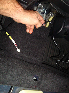
 That little white connector by my hand is the navi connector...
 - So, this is a good time to disable the video lock on the navi unit. It's easy...There is a grey wire...cut it about 3 inches from the connector. Splice on a wire lead about 20" long to the connector side (3" length). If you have them, splice on a ring to the end of the new lead for grounding to the stereo chassis later.
 Remember, connect the lead to the end of the cut grey wire that leads to the connector! IF you do it wrong, your ebrake light will be on all the time:( You see here the yellow with oragnge stripes wire...that's the one I spliced onto the grey wire.
 - Okay, Now we have to splice in power, switched power and the dimmer. For what it's worth, I have wired this three different times in at different points in the whole scheme. The first time was done in a way that made complete logical sense...which left the unit on all the time, even though it was wired correctly.
- So after a couple of other attempts, I discovered the fused power for the control box DOES NOT wire to constant fused power in the car. It is wired to the swtiched accesory power. It is the only way the unit will shut off when you shut the car off. Why is this important? Well, if you leave your car in the garage for 4 days, you will have a warm glove box...and really that is a janky mode of operation.
- Anyways, the switched accesory power is pin 10 on a navi and pin 3 on a std. head unit. If you look real close on the back surface of the connector, you will see the numbers there. And of course it's easy to recognize the BIG main connector on the back of both units. Reference this diagram...wiring diagram So hopefully you have the fused power line from the control box wiring harness wired to the switched accesory power on the head unit.
- Now the dimmer lead on the control box wire harness will be wired to the dimmer pin on the navi unit. Unfortuantley, the dimmer circuit on our cars are inverted, so it works backwards. Whicih means, with your lights off, it's in dim mode, with your lights on its bright. There is nothing you can do about this unless you want to go through the hassle of wiring in another inverter circuit. Fuck that. it works fine the way it is. So find pin number 1, and splice it to that...it applies to both the navi unit and the std. head unit.

- Now it's time to connect the groudn to the navi chassis. If you look on the right side of the chassis, there is already a ground wire there. Simply take the ring lanyard from the control box harness and connect it to one of the other screws. Also, this is the time to connect the other ground lead you made earlier from t he navi connector so you can watch movies while driving. should look somethign like this.
 The grey wire is the stock ground, the balkc is the Econ ground, and the yellow oarange stripe is the wire lead I made that goes back to the navi connector's grey wire.
 - Fedd the control box wiring harness through the back and to the right in the headunit space so it drops into the glove box...it's pretty easy.
 Centered in the picture, immediately right to the white conenctors, you see the red, oarnge and yellow wires running into an area that leads into the glove box that is directly to the right (not shown).
 - So now, in the glove box, you should have all the wires coming in from the four corners of the car and control box wiring harness. Here you see my temporary bundling.

- Now what I did was use the velcroe strips for mounting the control box and dispaly to the top surface of the glove box. Find your positions and to a mock up mount to measure your slack needed for connections. Again, cut the extra slack to length and hand solder the wires together so you have a 1 ft long wire bundle to tuck away.

- You can see from the picture directly above, that after you take out all the slack and are sodlered up, simply zip tie or use electricians tape to bundle the now 1 ft' harness together, and you can stuff them in the pocket shown above...shown right where the cables are coming through in the pic above.
- Almost there...simply plug all the lines in the back of the control box, connect the display interface to it and moutn to the velcroe strips...
- As you can see below, the display interface cable is tucked behind, and you can use more Velcro, to tie it up high.

- Put the key in the ignition and turn it to on(don't start your car).
- You will hear all the motors do a diagnostic and the display will light up. FYI, mine did this and shut down afterwards, it took me a week to figure out that it was in valet mode. So if htis happens to you, simply press both "mode" buttons simultaneously when initially turning it on and it will exit valet mode.
- FYI, evrything has to be plugged in to work...so don't waste your time until you have everything connected.


